Create base panel
Icon |
Menu bar |
Keyboard shortcut |
|---|---|---|

|
File > New |
Ctrl + N |
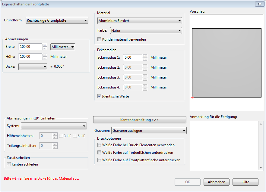
In the Front panel properties dialog, you specify the basic shape, the Material., the edge design, and some other basic options. You can open and edit this dialog again later at any time via the file menu with the key combination Ctrl + F or by double-clicking the front panel.

Parameters |
Description |
|---|---|
Basic shape |
Choose between a rectangular and elliptical front panel shape or read in a DXF file with the outer contour of the front panel (Free contour from DXF file). Note: Even if the front panel already contains inner contours (milling elements), the function Free contour from DXF file will only read in the outer contour. You can learn how to import the entire front panel at once, here: Create a new file from DXF file. Tip: The outer contour is milled using a tool diameter of 3 mm. If the contour contains finer details that cannot be realized with this cutter, the milled contour will differ from what is drawn. However, you have the option of inserting additional milling objects in these areas, for which you set smaller cutters. |
Dimensions |
Here, you enter the front panel’s width and height. If a DXF contour was used as the basic shape, the width and height of the rectangle enclosing the shape are displayed; in the case of a DXF contour, these cannot be edited. The material thicknesses available for selection depend on the chosen material and refer to the panels Schaeffer AG has in stock. If you require other material thicknesses or panel dimensions, please contact the customer service team. |
Dimensions for 19” systems |
Here, you can set the dimensions of your front panel in units of height and pitch that are suitable for 19” rack systems. The resulting values in “mm” are displayed under Dimensions. |
Edge grinding |
Here, for rectangular panels, you can order the grinding of the outer edges (end faces) at a fixed price. |
Material |
Here, you can choose from the available standard materials.
You can find more information about these and other materials, here: Material. Note: If you want to use a material other than what is listed, leave the material as the default setting and write which material you want in the field Remarks for production. |
Color |
Depending on the material, there are several standard colors to choose from. For other colors, write a corresponding note in the Remarks for production field or contact the customer service team. |
Use customer-supplied material |
If you would like to provide your own material or semi-finished part, check the box next to this option. |
Corner radii |
With the corner radii, you can determine the outer radii of a basic rectangular shape’s four corners. To create different corner radii, remove the checkmark from the box next to Identical values. |
Edge machining |
The outer edge of both the front and reverse sides of the front panel can be optionally designed with a circumferential bevel or rounding. Note: For manufacturing reasons, an unmachined strip of at least 0.6 mm must remain on the end face between the edge machining on the front and reverse sides. |
Engravings |
Here, you make the global settings for all engraving elements contained on the front panel (only relevant if the front panel contains labeling elements). Only mill engravings: Engravings are not in-filled with color but rather remain “blank”. In-fill engravings: Standard setting. Engravings are milled and in-filled with engraving paint. You specify the color in the respective engraving’s properties dialog. Print engravings: Engraving elements are not engraved but rather applied to the front panel using the UV printing process. This option is only available for our anodized aluminum. The engraving settings apply to all engraving elements (HPGL, text, and line engravings) of the front panel in question. You can change the engraving settings for each individual engraving element in its properties dialog regardless of the global setting made here. |
Printing options |
Here, you make the global settings for all print elements contained on the front panel (only relevant if the front panel contains print files). Use white ink for print elements: If this option is selected, the print file’s white areas will be printed white. Front Panel Designer can distinguish between white and transparency; is not necessary to create special (spot) colors in the templates. Underprint white on areas covered by ink: If this option is selected, all printed areas will be underprinted with white as a neutral color. The actual print is applied subsequently. This option is especially recommended for colored material as well as for displaying light colors. This option allows you to maintain the color fidelity and brightness of your graphics. Underprint white ink on front panel surface: With this option, the entire surface of the front panel is printed white, including unprinted areas. This option also allows you to maintain the color accuracy and brightness of your graphics. You can find more information in the Graphics section. |
Remarks for production |
Notes and information on requirements that cannot be mapped directly in Front Panel Designer but can still be implemented belong in this field. The text you enter here will be taken into consideration by our order processing and production teams. In particular, you can use this field to provide information about:
|
