End face machining
The front panel’s end faces can also be machined. To use this option, proceed as follows:
Create an additional file for each end face to be machined. This file contains a top view of the end face concerned. For the width and height, enter the actual dimensions of the end face. Leave the standard settings for the material. For the thickness, select the largest possible material thickness (10 mm).
Position the desired elements on the front panel.
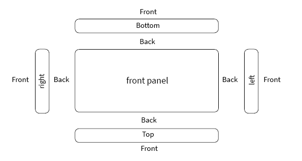
Note on orienting the end face file: Draw the top view on the end face. To avoid misunderstandings and to make it easier for our production team, it helps if you make a sketch and attach it to your order, for example, as a PDF file.
Below is an example of how you can sketch and label your front panel for us, including the end face machining:
As a 2D sketch

Or as a 3D sketch

Placing elements during end face machining
Note: There should be at least 1 mm of material left around a blind hole. For example, to produce M2 tapped blind holes, the base panel should be at least 4 mm thick. No drill holes can be made in the area of the corner radii. Edge machining cannot be done on the end faces.
