HPGL engraving
Icon |
Menu bar |
Keyboard shortcut |
|---|---|---|

|
Insert > HPGL engraving |
H |
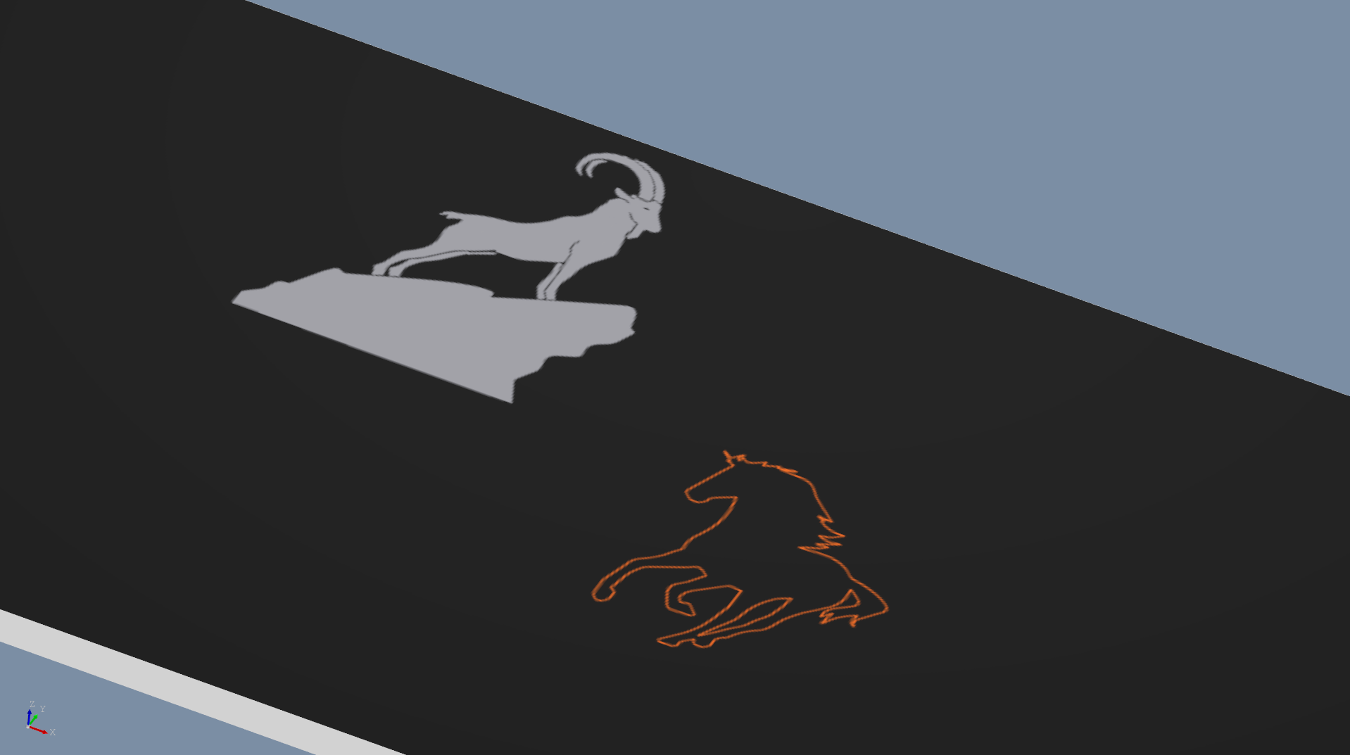
The HPGL engraving function enables you to have a freely designed contour engraved on the front panel. A file in HPGL format (Hewlett Packard Graphics Language; file extension .plt) is required for this.

Function properties
Parameters |
Description |
|---|---|
HPGL file |
Select the desired HPGL file from the suggestion list or read it in from your storage location. |
Pen assignment |
When creating an HPGL file, each line must be assigned to a “pen.” In this dialog, you now assign an in-fill color and a tool from the assigned drop-down lists to each of the pens. |
Reference point |
You have the following options for choosing the reference point:
|
Rotation angle |
Rotation angle of the HPGL file around its reference point. |
Scaling |
Here, you can change the size of the engraving’s appearance. The current size is displayed at the bottom of the preview. Note: Especially with filled surfaces, scaling only leads to good results to a limited extent since the distance between the cutter paths is not adjusted, but rather is only scaled. This can lead to gaps in the engraving image, for instance, when it is enlarged. |
Mirror |
Mirrors the HPGL contour on the vertical axis via its reference point |
Place on reverse side |
Check the box next to this option if the engraving should be made on the reverse side of the panel. Please note that the appearance of the engraving element on the reverse side will be mirrored, and if necessary, check the box next to Mirror. In Front Panel Designer, the front panel will always be depicted in the frontal view. |
Cut after surface finishing |
Only for powder-coated panels. Check the box next to this option if the engraving is to be made after powder-coating. For more information, see Subsequently milling elements. |
Do not produce element |
When the box next to this option checked, the element appears in the file for informational purposes only, but will not be produced. For more information, see Non-produced elements. |
Print/In-fill |
Here, you determine whether the engraving in question is to be printed or in-filled. The global setting from the front panel’s properties dialog is used by default. |
