Free contour
Icon |
Menu bar |
Keyboard shortcut |
|---|---|---|

|
Insert > Free contour |
X |
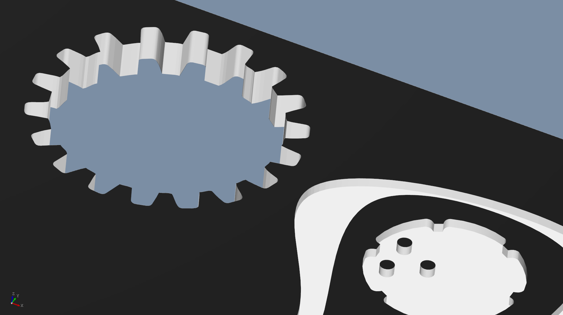
Free contours are milling elements with a freely designed contour. The contours must be available as self-contained Closed lines in DXF format. The DXF file can contain one or more of these lines. The free contour can be designed as a cut-out or cavity.

Function properties
Parameters |
Description |
|---|---|
DXF file/Reading in |
Select the desired DFX file from the suggestion list or read it in from your storage location. The display size of the object to be placed is displayed at the bottom of the preview. |
Update |
This button can be used to directly apply subsequent changes to a DXF file that has already been imported. |
Reference point |
As reference point, you can choose a) between five points of the objects’ rectangular outline, b) the DXF file’s origin, and c) the cross included as reference point in the DXF file (see below: “Freely definable reference point”). |
Rotation angle |
Rotation angle of the free contour around its reference point. |
Scaling |
Here, you can change the size of the contour’s appearance. The current size is displayed at the bottom of the preview. |
Mirror |
Mirrors the contour on the vertical axis via its reference point |
Design as cavity |
Check the box next to this option if you do not want the free contour to break through the material. Then, set the desired depth and, if necessary, the placement of the cavity on the reverse side. |
Tool |
The 3 mm cutter is set by default. To produce smaller inner radii, select a smaller tool if necessary (this may result in higher costs due to tool changes). Deviations between the free contour and the cutter path are indicated by red lines in the preview. |
Cut after surface finishing |
Only for powder-coated panels. Check the box next to this option if the free contour is to be made after powder-coating. Additional information. |
Do not produce element |
Check the box next to this option if the element is not to be machined but rather placed on the front panel for information purposes only. |
Edge machining |
The edges on the front and, if necessary, reverse sides can be bevel or rounded. |
Freely definable reference point
You can define a reference point for the free contour by drawing in a cross consisting of two straight lines with a length of approx. 5 mm in the DXF file. When importing, this cross will be recognized and, if necessary, offered in the properties dialog as an additional option for the object’s reference point.
Free contour with multiple closed lines
Milling elements that contain multiple closed lines are automatically split and then grouped immediately after import. If necessary, you can ungroup and edit the individual elements, regroup them, or combine them into macro elements.
Tip: Any split free contour element can be directly selected for editing without ungrouping them via Ctrl + left-click.
If individual elements cannot be machined with the initially selected tool (for instance, because the contour is too small), automatic tool adjustment occurs. In such a case, the program issues a corresponding message.
You can assign a tool to each line individually.
Deviation between free contour and cutter path
The attainable contour may deviate from the original contour, especially with small inner radii or small opening angles. You can see the differences in the preview window. The original contour is displayed in a dashed red line.
Alternatively, you can use the outline mode (Ctrl + D) to make the differences visible, even after inserting them.
The contour can be refined by selecting a smaller tool diameter. When doing so, note that additional costs will be incurred due to the tool change as well as longer milling times (when selecting smaller tool diameters).
